Appendix VI – RE Measurement
The RE board system is a subsystem of the Inspector. It is responsible for calculating earth resistance and loop impedance based on Neutral, Line (Phase 1), and Earth signals.

- The RE system runs with the following sequence (Non-Tripping mode):
- The main board sends a data request frame to the RE board.
- RE system sends Acknowledge frame to Main board to validate it received a request from main board.
- RE system calculates required data using two techniques:
A. L/N shorting Technique:
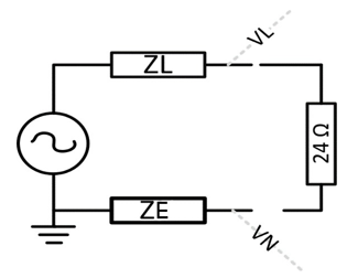
This technique aims to measure ZL (Line Impedance) and ZN (Neutral Impedance) by following the next steps: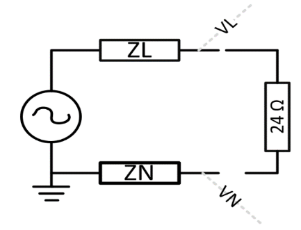
- Signal Control and Sampling:
Measure the instantaneous unloaded and Loaded voltages of Line and Neutral, VL(Unloaded), VN(Unloaded), note that all voltage measurements on LLRE are with respect to Earth.
- Drive both phase control relay and the safety relay high.
- Capture LE (Line to Earth) and NE (Neutral to Earth) instantaneous voltages with sampling rate (4882.8125 Ksps).
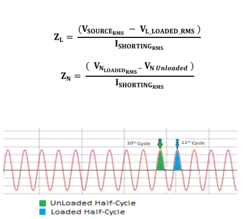
- Compare each two successive samples of Line samples to detect the Second-Zero-Crossing of Line instantaneous voltage signal by comparing the sign change between each two successive samples.
- At the 10th Second-Zero-Crossing, store Half-Cycle number of samples of Line and Neutral to get the Unloaded voltages.
- At the 11th Second-Zero-Crossing, give a driving pulse to the Thyristor of a time between (15-20 millisecond) to conduct the L/N Shorting technique while storing Half-Cycle number of samples of Line and Neutral to get the Loaded voltages.
2. Signal calculations:
Perform calculations to determine the required ZN and ZL values.
Find VL(Unloaded_RMS), VN(Unloaded_RMS) by doing the following:
- Calculate average values of LE and NE unloaded voltage samples and LE and NE loaded voltage.
- From average values calculate RMS values.
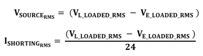
- Using calculated average values calculate VSOURCE_RMS and ISHORTING_RMS values according to these equations:
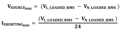
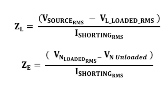
Where 24 Ω is the shorting resistance value. - Using the above calculated values calculate ZL and ZN according to these equations:
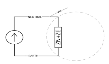
B. Current injection technique:
This technique aims to calculate the accumulated (ZE + ZN) impedance.
- A small test current is injected between Neutral (N) and Earth (E).
- The injected current flows through the earth path and returns through the neutral conductor, forming a loop that includes the earth impedance and the neutral impedance.
- The resulting voltage between Neutral and Earth is measured.
- Using the injected current and the measured voltage, the system calculates the accumulated impedance:
Z total = ZE+ZN
- Since the injected current is kept below the RCD tripping threshold, the RCD does not trip during the measurement.
- The RE system runs with the following sequence (Tripping mode):
- Main board system sends Data request frame to RE board.
- RE system sends Acknowledge frame to Main board to validate it received a request from main board.
- RE system calculates required data using two techniques:
A. L/E shorting Technique:
This technique is used to measure ZL (Line Impedance) and ZE (Earth Impedance).
- Signal Control and Sampling:
Measure the instantaneous unloaded and Loaded voltages of Line and Neutral, VL (Unloaded), VN (Unloaded),
note that all voltage measurements on LLREare with respect to Earth.
- Drive both phase control relay and the safety relay high.
- Capture LN (Line to Neutral) and EN (Earth to Neutral) instantaneous voltages with sampling rate (4882.8125 Ksps).
- Compare each two successive samples of Line samples to detect the Second-Zero-Crossing of Line instantaneous voltage signal by comparing the sign change between each two successive samples.
- At the 10th Second-Zero-Crossing, store Half-Cycle number of samples of Line and Earth to get the Unloaded voltages.
- At the 11th Second-Zero-Crossing, give a driving pulse to the Thyristor of a time between (15-20 millisecond) to conduct the L/E Shorting technique while storing Half-Cycle number of samples of Line and Earth to get the Loaded voltages.
2. Signal calculations:
Do some calculations to measure the required ZN and ZL values.
Find VL(Unloaded_RMS), VN(Unloaded_RMS) by doing the following:
- Calculate average values of LE and NE unloaded voltage samples and LE and NE loaded voltage.
- From average values calculate RMS values.
- Using calculated average values calculate VSOURCE_RMS and ISHORTING_RMS values according to these equations:
Where 24 Ω is the shorting resistance value.
- Using the above calculated values calculate ZL and ZN according to these equations:
B. Current Injection Technique
- Signal Control and Equations for Generating Injected Current:
- Inject a known very small AC current -to avoid RCD tripping- directed from neutral to earth through:
- Connecting the Neutral point to the Current Injection point using LN, N-PE Impedance Switch Relay.
- Generating the injected current by:
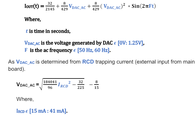
- Generating a voltage through the external DAC that has the following formula:
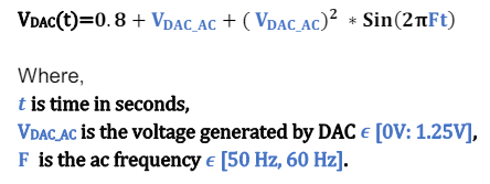
- As this voltage will be converted to a current signal that is described by following formula:
2. Signal Capture and calculations:
Capture Neutral Signal and do some calculations to measure the required ZE value as follows:
- Measure Neutral Voltage instantaneously and capture specific number of samples per cycle according to system memory limitation and value accuracy.
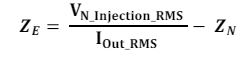
- Calculate VN_Injection_RMS by using the RMS formula from the sampled Neutral Voltage Value.
- Calculate ZE from the following equation:
- Using the calculated parameters from the previous two techniques, prepare the required data to be sent.
|
Required Parameter |
Formula |
|
Loop Impedance ZLOOP |
ZL + ZE |
|
Loop Prospective Fault Current (L-PE PFC) |
VSOURCE_RMS / ZLOOP |
|
Line Impedance ZLINE |
ZL +ZN |
|
Line Prospective Fault Current (L-N PFC) |
VSOURCE_RMS / ZLINE |
|
Earth Resistance |
ZE |
- Send measurements results frame to main board.
- Reinitialize system and wait for another request data frame to run the whole sequence again.
Created with the Personal Edition of HelpNDoc: Say Goodbye to Documentation Headaches with a Help Authoring Tool