Per-channels Parameters
- Select the second tab, Channels Configuration, to configure the channel settings.
- Use, Display Name, field to modify the channel name.
- The Identifier field allows you to specify whether the readings are taken before or after the UPS.
Note: if “No UPS “is selected initially, this option will be disabled. - Use Enabled option to activate or deactivate the channel.
Note: Disabling a power channel stops all monitoring for that channel. No readings, trends, or power quality events will be generated for disabled channels.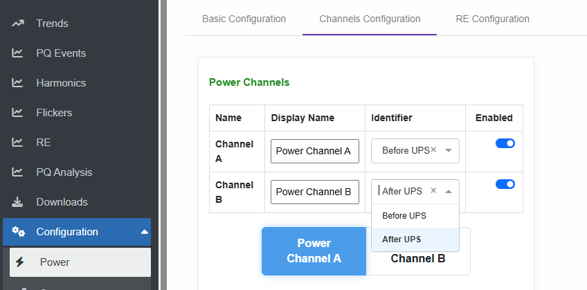
- Select the channel to configure its specific parameters.
These parameters must be configured individually for Channel A and Channel B.
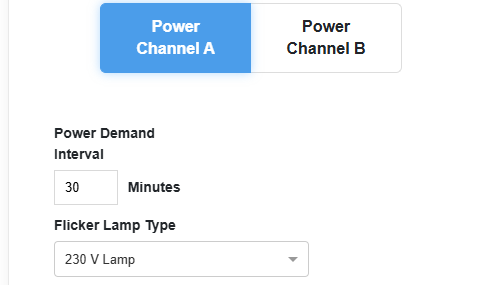
- Set Demand Time on which the system calculate the average power demand across the set period.
- Choose Flicker Lamp Type to be either 230 V Lamp or 120 V Lamp.
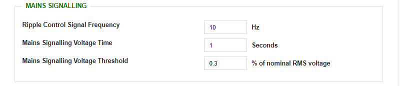
- Configure the parameters of the desired ripple control signal to enable monitoring and generate an alert if the signal exceeds the defined limits, including:
- Signal frequency
- Voltage time
- Voltage threshold percentage
- Set Events threshold and hysteresis
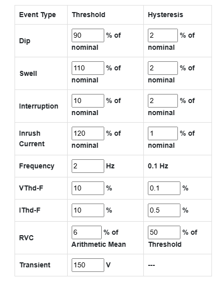
- The Dip, Swell, and Interruption event threshold and hysteresis values, are percentage of the Nominal RMS Voltage configuration value.
- The Inrush Current event threshold and hysteresis, are percentage of the Nominal RMS Current configuration value.
- The VThd-F and IThd-F event threshold and hysteresis value is exact THD values, which is by definition a percentage value.
- The RVC (Rapid Voltage Change) event threshold, is a percentage of the arithmetic mean of the last 100/120 RMS ½ values depend on the frequency set. (100 for 50Hz, or 120 for 60Hz configuration)
- The RVC hysteresis value is a percentage of the RVC threshold itself.
- The Transient event threshold is a raw signal voltage value in Volts.
Created with the Personal Edition of HelpNDoc: Simplify Your Help Documentation Process with a Help Authoring Tool