RVC Event
Overview
An RVC (Rapid Voltage Change) event is an abrupt transition between two steady-state RMS voltage levels in an electrical power system.
Unlike dip and swell events, RVC events do not exceed predefined voltage thresholds. Instead, they represent a rapid shift between two stable voltage conditions.
An RMS voltage is considered to be in a steady state when the most recent 100/120 Urms(1/2) values remain within a defined threshold around their arithmetic mean (100 values for 50 Hz, 120 values for 60 Hz).
The RVC threshold is configured as a percentage of a reference voltage and defines the allowable variation within a steady-state condition.
The RVC threshold is set by the user according to the application, as a percentage of the reference.
RVC Detection Method
The RVC detection process operates as follows:
- An initial set of 100/120 Urms(1/2) values is recorded.
- The arithmetic mean of these values is calculated to define the steady-state reference.
- For each voltage channel, a logical signal (voltage-is-steady-state) is generated:
- TRUE: when the voltage remains within the RVC threshold around the calculated mean.
- FALSE: when the voltage deviates beyond the threshold.
- This logical signal is updated continuously as new Urms(1/2) values become available, and the arithmetic mean is recalculated using the latest 100/120 values.
- In polyphase systems, a combined steady-state signal is generated as the logical AND of all channel steady-state signals.
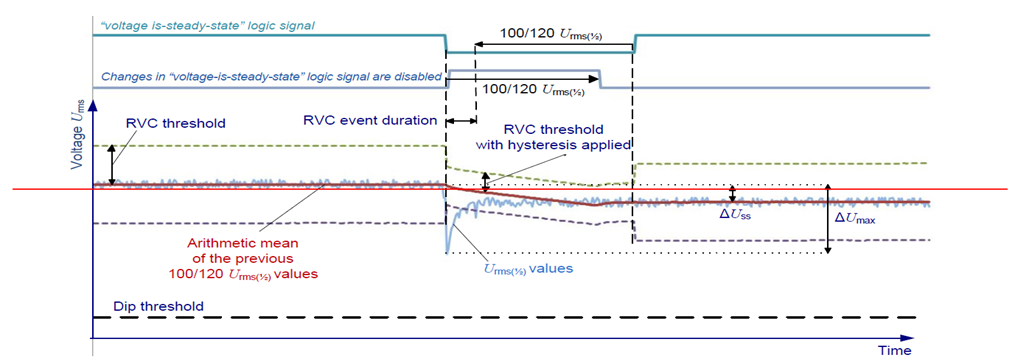
- An RVC event starts when the steady-state signal of any voltage channel changes from TRUE to FALSE.
- During the event, the reference mean continues to be updated dynamically
- When the voltage returns within the RVC threshold (including hysteresis) of the newly calculated mean, the steady-state signal returns to TRUE.
- An RVC event ends when the steady-state signal returns from FALSE to TRUE.
- After the event ends, the RVC hysteresis is temporarily applied (disabled for 100/120 half cycles) to ensure a stable steady-state condition
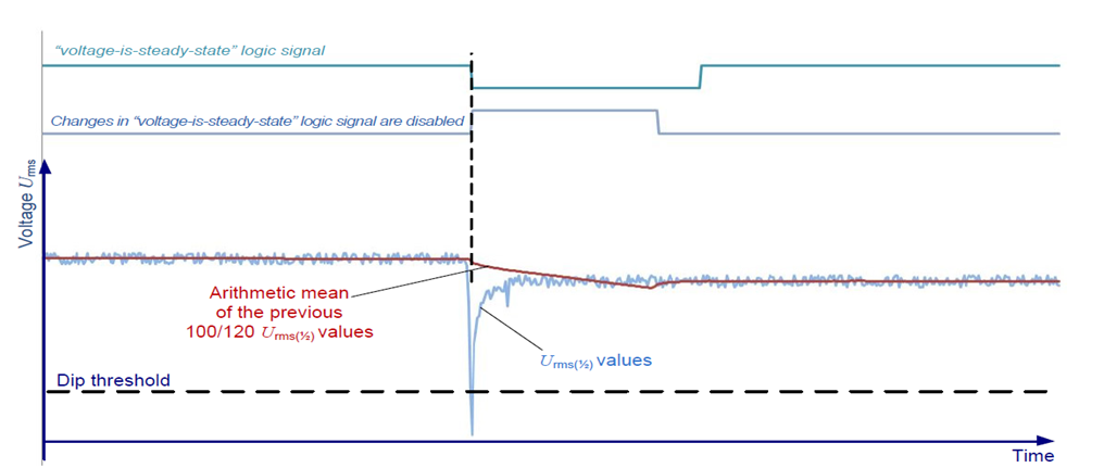
- If a dip or swell event is detected during the RVC detection process (including the disable period), the RVC event is discarded.
RVC Measurement Specifications
1. Measurement Method: RVC events are detected when a transition occurs between two steady-state RMS voltage levels without exceeding dip or swell thresholds.
2. Recorded Event Information
- Voltage Level: Urms(1/2) at event start and end.
- Phase: Corresponding phase(s) at event start and end.
- Start Time: Event start timestamp.
- Frequency: System frequency at event start.
- Event Duration: Time interval between event start and end.
- Worst Case: Minimum Urms(1/2) value recorded during the event.
- Delta Us: Absolute difference (V) between the average RMS voltage before and after the event.
- Delta Umax: Absolute difference (V) between the worst RMS value during the event and the pre-event average.
3. Event Threshold: Defined as a percentage of the reference RMS voltage.
4. Event Start: Beginning of a transition where the voltage leaves the steady-state condition.
5. Event End: Beginning of a transition where the voltage reaches a new steady-state condition.
6. Event Discard: The RVC event is discarded if a dip or swell event occurs during detection.
7. Polyphase System Treatment: An RVC event starts when any phase loses steady-state condition and ends when all phases return to steady state.
8. Stored Waveforms: Event waveforms are recorded for each detected RVC event.
Created with the Personal Edition of HelpNDoc: Full-featured EBook editor