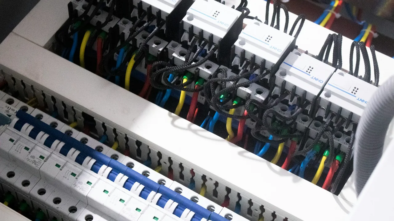
A factory plans another production line. A campus adds a chiller. A warehouse adds a shift. Someone has to answer a simple-sounding question: can the existing electrical infrastructure take it?
Two shortcuts usually answer it, and both are unreliable. Adding up nameplate ratings almost always says “upgrade”, because loads rarely run at full rating together. Occasional meter readings often say “plenty of spare capacity”, because they were taken at a quiet moment. Neither reveals coincident demand, phase-specific limits, or the supply conditions during the period when the new load will actually run.
The question to answer
Where is capacity really available, and what constraint will the new load expose?
The measurement plan
- Start from the single-line diagram. Identify the incomer, the critical feeders and the point where the new load will connect.
- Survey representative periods — weekdays, weekends and each operating mode — rather than an arbitrary short visit.
- Keep the quantities together: phase currents, power, voltage, events and environmental context.
- If you survey locations one after another, record production changes that could make a direct comparison invalid.
The Portable V4 is built for this kind of structured, repeatable survey: it is the same measurement engine as the fixed Inspector V4, with a 7″ touchscreen, two isolated channels and a six-hour battery, so survey evidence is of the same grade as a permanent installation.
Reading the evidence
- Separate average utilisation from coincident peaks — the periods when several large loads run together.
- Find the real constraint. Is it a particular phase, a feeder, an operating schedule, or a supply-quality condition such as voltage drop at peak?
- State what was not measured. Spare capacity cannot be declared from current alone without checking cables, protection, the transformer, thermal limits and site design constraints.
A survey supports design; it doesn’t replace it. A monitoring survey is not a protection-coordination study, a cable-rating calculation or an electrical safety certificate. Give the designers measured profiles and boundary conditions, not a green or red light.
Acting on the evidence
Present a prioritised options report. Depending on the data, options include:
- redistributing suitable single-phase loads to relieve a heavily loaded phase,
- staggering the operation of large loads,
- investigating poor connections that show up as heat or voltage drop,
- addressing disturbance sensitivity before the new load arrives,
- or commissioning a detailed capacity study where the margin is genuinely tight.
After the expansion, repeat the relevant baseline measurements to confirm the infrastructure behaves as predicted.
A good result might be a better-targeted upgrade, or a justified decision to keep the existing infrastructure. It is not necessarily an avoided investment — and should not be sold as one.
A closer look: busway and switchroom hot spots
Expansions often push distribution busways and tap-offs harder than before, and a temperature alert from a joint is a common first symptom. An isolated temperature alarm cannot distinguish sustained loading, rising ambient temperature, a sensor placement effect or a developing connection problem.
Measure temperature against load, not temperature alone:
- Document each measurement location and the circuit it represents.
- Combine phase loading with a temperature channel at the joint or enclosure, plus an ambient reference.
- Confirm sensor attachment, insulation, calibration and channel naming — and use only hardware rated for the mounting location.
- Compare temperature rise above ambient at similar load, and compare locations only when their geometry and cooling are comparable.
A changing load-temperature relationship is a reason to investigate. Check whether the thermal change persists when the load returns to a previously observed operating state — if it does, schedule an inspection by an authorised electrical team using the appropriate safe process. After maintenance, repeat the monitoring with the same sensor positions so the comparison stays meaningful.
Inspector’s Panel Mount models combine AC power quality with temperature inputs, which suits permanent monitoring of distribution boards and busway sections.
A point sensor sees one point. It does not survey every joint, and monitoring does not replace protective devices or safe inspection. Confirm sensor count and busway integration for the deployment.
What to measure to show value
- survey coverage of the operating modes that matter,
- design assumptions replaced by measured evidence,
- peak loading per phase,
- post-expansion performance against the survey,
- thermal alerts, time from alert to inspection, and recurrence after corrective work.
Related reading
- Building a defensible power quality baseline
- Harmonics and poor power factor
- What a power quality analyzer actually tells you
Planning an expansion?
An engineer will tell you which points to survey, for how long, and what the report should contain. Book a meeting